Milk Drying Technology - 3 Stage Spray Dryer
The discovery of spray drying constituted a very important advance in the production of heat sensitive dry products, allowing the drying of solutions in a very short time and with relatively low product temperatures. Large scale application of this process began in the 1920´s, mainly focused in the dairy industry and the production of detergents. Since then, there have been a series of improvements such as the vibrating fluid bed dryer to finish the drying process outside the chamber and the fines reinjection for simultaneous agglomeration and drying, which helps obtain high dispersability products. Nevertheless, one of the most important advances has been the incorporation of a static fluid bed at the bottom of the drying chamber, giving birth to the so-called 3 stage-drying process.
Comparison between a conventional 2 stage spray dryer and a 3 stage spray dryer
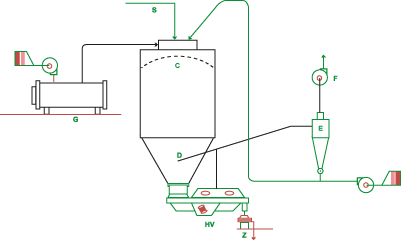
Description and working principle of a conventional 2 stage spray dryer (Fig. 1)
An air current heated in hot air generator G enters the drying chamber C through the top. Previously, it flows through a circular duct and it is distributed in the chamber by means of a maze duct system. As a consequence of following this path, the hot air flows with a rotational movement and is evenly distributed in the whole chamber. Simultaneously, the drying solution is introduced, which in most cases is a liquid solvent with a defined amount of solids dissolved in it. The main function of the drying chamber is to eliminate the solvent by evaporation and to retrieve the powder formed by the dissolved solids.
The drying solution (S) enters the chamber through an atomizing device that consists of a rotating disc spinning at very high speed (around 10.000 RPM) that sprays the liquid feed.
The plant configuration is such that the hot air meets the liquid mist. This happens at the top of the chamber, very close to the roof. The mix of hot air and thinly pulverized liquid is the fundamental principle of a 2 stage drying chamber, given that under these conditions a fast evaporation of the solvent is produced (water in most cases). As a consequence of this fast evaporation process, the solids contained in the solution are dried at a low temperature despite the air is entering the chamber at temperatures ranging 160°C to 250°C, depending on the product that is being processed. Heat sensitive elements, such as milk solids, vegetable extracts, proteins, colorants, preservants, etc. are dried at temperatures around 50°C to 60°C and with a very short residence time (15 to 30 seconds).
Solids continue to dry inside the chamber, dragged by the air heading for the exit duct towards the cyclone. From there the air is eliminated to the atmosphere by a suction blower.
As for the powder produced, it is divided into two flows:
- The coarser and heavier particles in an advanced drying state, fall into a vibrating fluid bed dryer (Hv) where they reach their final moisture. The exit of the fluid bed dryer is the end of the drying process where the powder is collected after going through a screener (Z).
- The fines are dragged by the air current on its way to the cyclone that separates them by centrifugal action. The fines fall to the bottom of the cyclone where it is dragged by another air current and reinjected into the chamber for agglomeration and increased wettability, given that the powder exiting the cyclone is too fine and this undermines some of the its qualities like dispersability.
Figure 1

As described before, in this type of chamber the drying process is Split in 2 stages. The first stage happens in the proper drying chamber and the second in the fluid bed dryer that gathers the powder exiting the chamber. This fluid bed receives a hot air current that has two functions: fluidizing the product and finish the drying process (2nd stage)
The drying in the chamber includes the drying stage at constant speed and temperature very close to wet bulb temperature and in most part a drying process at a diminishing speed by diffusion which forces to keep high temperatures for the exiting air. As it will be explained when addressing the 3 stage spray dryer, this hot air exit current is one of the main differences between them that favors lower energy consumption given that exit temperature for air is lower in 3 stage drying.
Figure 2
Description and working principle of a conventional 3 stage spray dryer (Fig. 2)
The general configuration of a 3 stage spray drying plant is similar to the 2 stage dryer regarding:
- Hot air generation (G)
- Hot air inlet into the chamber
- Liquid inlet through the rotary atomizer
The main difference is the addition of a static fluid bed (K) inside the chamber where the poder coming from the 1st stage falls with high moisture. Until then, only the outer moisture of the particles is evaporated in a very short time of around 20 seconds, where drying temperature is constant an very close to wet bulb temperature of the air which is very low (approximately 40°C).
The second stage of drying consists in the injection of hot air into the chamber at the point where the first stage ends. In the static fluid bed the core moisture if the particles is evaporated. This process requires more time, and the still humid fluidized powder is agglomerated while it is being dried. In the third stage, the powder finishes the drying process in a vibrating fluid bed dryer and is cooled to packaging temperature.
With the combination of these 3 stages, drying is split into two systems specifically adequate for the water content of the particle at each moment. The surface moisture is eliminated during the path of the powder inside the chamber and the core moisture is eliminated while the powder is in the static fluid bed. The air required to fluidize the powder is produced by a hot air generator (J). This air current enters the fluid bed through a specially perforated sheet. Once the drying is complete the powder can be cooled by means of a vibrating fluid bed dryer (Hv).
Comparison between the working principle of a conventional and a 3 stage drying chamber
The following issues are addressed:
- Energy balance
- Dry powder characteristics
- Equipment size
- Operational flexibility
- Operational stability regarding constant moisture, density and particle size in the final product
- Cleaning of the equipment
1) Energy Balance: the heat energy required by a 3 stage chamber is approximately 10 % to 20 % less than the necessary for a conventional 2 stage dryer with the same output capabilities. To analyze the thermal issue a global thermal yield for an adiabatic process is defined as:
Yield: = (T in - T sat out) x 100 / T in – T amb
T in = inlet temperature of drying air
T sat out = outlet adiabatic saturation temperature for the drying air
T amb = ambient temperature
As it can be appreciated, for the same inlet temperature and constant ambient conditions, when lowering the outlet temperature of the drying air the thermal yield is increased. In a 2 stage plant the outlet temperature is around 85-90°C while in a 3 stage process it is reduced to 75-80°C
2) Characteristics of the powder: in a 3 stage system high density agglomerated powders can be obtained, with free-flowing and high dispersability qualities.
3) Equipment size: For the same production capacity, a 3 stage chamber should be shorter than a conventional one, reducing costs in civil works.
4) Operational flexibility: Both rotary and spraying nozzles can be used in 3 stage chambers, allowing a higher control of the product qualities.
5) Operational stability: Given that drying is produced in 3 stages that are designed for each different moisture content of the product, this type of system offers high operational stability.
6) Cleaning of the equipment: the internal geometry of a 3 stage chamber is especially apt for the use of CIP cleaning nozzles or spraying systems.